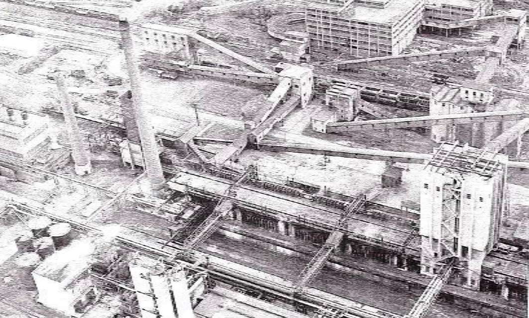
 The Nantgarw Coking Plant was the first coke oven scheme on an entirely new site to be completed by the National Coal Board. It was situated in the Taff Valley about seven miles from Cardiff and near the Nantgarw Colliery, which at the time was being newly developed. Since the war, South Wales had been importing from other districts blast furnaces and industrial coke at a rate of about 4,000 tons per week and the demand at that time was increasing. The new plant would have helped to meet this demand in pail; and replaced some of the smaller and obsolete coke oven capacity in addition to adding materially to the available gas supplies via the newly constructed East Glamorgan gas grid of the Wales Gas Board.
The plant was designed for a capacity of 1,500 tons of coal per day to produce about 1,100 tons of coke; in the own section, however, the installed capacity was a 1,000tons of coal per day initially and as soon as that was in operation the remaining ovens would be built.
Coal Handling Plant
Coal was received either from the washery at the Nantgarw Colliery or as washed coal from outside collieries. The coke oven handling system was equipped to handle coal below 2 inches and large coal above this size was to be crushed at the colliery washeries. Initially, the washery had a capacity of 350 tons pc hour with a 30” wide belt with a capacity of 200 tons per hour connecting the washery to the coke oven blending bunker but the conveyor gantry was so arranged that a second belt which terminates at the junction tower, can be extended to take coal from the second washery unit. There were ten blending bunkers, each of which held 200 tons. From these, a collecting belt first passed over a magnetic pulley – which removed any tramp iron – and then delivered the coal to either of the hammer mills of 160 tons per hour capacity each. From the hammer mills, conveyors of 160 tons per hour capacity ran to the top of the service bunker and delivered the coal onto a revolving shuttle belt. The service bunker had a capacity of 3,000 tons and was divided into two compartments, the lower slopes of which were glass-lined to promote easy discharge of the coal. This bunker was equipped with 24 mouthpieces of the quadrant type, arranged m four rows of six and with a ticket printing weighbridge below the charger car rails to record the weight of each charge.
Coke Oven Battery
The coke oven battery consisted of 72 ovens arranged in independent blocks of 12 so that when the ovens undergo repair, not more than one-sixth of the total plant capacity need be lost and gas supplies can thus be maintained. The daily throughput was 1,000 tons of coal, containing 9% of moisture, and the coking time was 18 hours. The load per oven was 15.7 tons of coal as charged.
The ovens were of the Simon-Carves’ Standard Underjet Twin Flue Compound type, with triple compartment regenerators, and were 44 feet 7 inches long over the sole times 12 feet 6 inches high and l8 inches mean width with charges 41 feet 9.5 inches long lines 11 feet 6 inches high and 18 inches wide. Giving a charge volume of 720 cubic feet calculated on the cold dimensions. Arranged for healing either by producer or coke oven. The chimney was 240 feet high and 7 feet 10.5 inches inside diameter at the top and was designed to draught 48 ovens when on producer gas thing. The top 30 feet were set in acid-resisting cement and the bottom 70 feet were lined with firebrick. Another chimney was added for the 24 extra ovens.
Oven Ironwork
The 72 ovens were braced longitudinally between two outer reinforced concrete buttresses and brick buttresses with 15W x 6W bracings were built between each of the six blocks of 12 ovens. The side platforms were below oven sole level and fitted with handrails, the top rail of which served as a compressed air main. All walkways were of reinforced concrete with granolithic finish and were supported independently of the buckstays by structural steelwork from the top of the waste heat flues.
Oven Doors
At the bunker end of the battery was a set station for oven doors, equipped with racks arranged so that doors may be lowered, by means of a 7.5 horsepower hoist, to a horizontal position for servicing; at the chimney end, there was a ram changing station with spare ram beam and leveller and guides and rollers. Door service hoists were also provided on the pusher machine and coke guides respectively.
Ascension Pipes
Each oven had two ascension pipes (both were fitted with steam ejectors to ensure smokeless charging) and liquor sprays in the bends; each block of 12 ovens had collecting mains on both ram and coke sides with cross-over connections. Two gas main bridges carried four sets of foul mains over the ram track to connect to the common main before the by-product plant. Each gas collecting main was pressure controlled, so that eight Askania regulators operated by pumping sets were located in control houses on the gas main bridges, and each man was fitted with a 16” bore flare pipe with quick acting liquor scaled valve.
Oven Machines
The pusher machine was of Messrs. Jas. Buchanan’s manufacture. The main carnage ran on eight travelling wheels, mounted in four pairs and running on cast steel pivoted cradles; the ram girder was of 30” x 12” box section with overdrive through rack, pinion, and worm reduction gear coupled to a 50 hp motor, the leveller beam was chain-driven through a 30 hp motor. The door extractor head could be slewed through 90 degrees and was fitted with Hopkinson gear for mechanically tightening and loosening the door latch screws. Heat shields are provided for door cleaning and a man hoist for door servicing. The coke side door extractor was also of Buchanan’s manufacture and, as in the case of the pusher machine, the extractor head could be slewed 90 degrees and was fitted with Hopkinson latch screw gear. The machine operated with a trailing guide of the retractable type and was fitted with a man hoist.
The coal charging lorry was of Messrs. Simon-Carves design. This machine was of the portal type with telescopic spouts and adjustable filler rings, vertical chain drives to the long travel shafts, and the motors and gearing mounted on the upper platform The hot coke car, was 40 feet long between the end plates and was carried on heavy, four wheeled, 66 inch wheel base bogies; the coke car locomotive was an 80 hp machine with casting house brakes, the compressor for the brakes also provided the air supply for operating the coke car discharge door cylinders.
An Avery ticket printing weighing machine was incorporated into the coal lorry track below the service bunker. Coal spillage was handled by a hoist of the self-landing and locating type, which collected spillage from a hopper on the pusher machine and returned it to any one of the four charging car hoppers. This hoist which extended over both the rain and coke sides of the battery car, could also be used to convey spares to the oven tops – including if necessary, one complete hopper for the charging car. Between the coke guide and the pusher machine, an electronic link is fitted and consists of a transmitting lamp on the guide and a receiver on the ram. Unless the guide was properly located with the door removed, no signal could be transmitted and unless the ram was correctly placed to receive the signal it could not operate.
Coke Quenching
After quenching the coke was tipped onto a wharf 200 feet long, whence it ran off to the wharf container through hand-controlled gates. The gates were operated from a reinforced concrete platform above the conveyor gully and a water service and hoses were provided for spot quenching.
By-product Plant
This plant up to the purifier inlet was designed to deal with about 16.5 million cubic feet of coke oven gas daily. It was arranged on the indirect ammonia recovery system to manufacture semi-pure 25% concentrated ammonia liquor. The gas leaving the ovens was in the common foul gas main had the tar and liquor trapped off at the downcomer into a tar catch tank, which was provided with slow-moving scraper conveyors immersed in the liquid. The primary gas coolers were of the vertical tube type, and three were installed- each of 25,500 square feet capacity and one on standby – The water supply was controlled by thermostat-operated valves. The exhausters were driven by steam turbines at 200lbs per square inch and passing it out at 25lbs per square inch for process use. A secondary gas cooler of the same type followed the exhausters but this had the casing strengthened and flash tube plates so that the tubes could be washed with light tar if required There were two electro-detarrers with independent static rectifier units, and four static ammonia washers of six stages each arranged to give two streams of 12 stages in parallel Cool virgin liquor from the primary gas coolers was added at the suitable intermediate stage. Tower scrubbers 102 feet high x 12 feet diameter were provided for Benzole scrubbing. After the scrubbers, the return gas main branched back to the ovens and the 1 gas went to the purifiers and was diluted with producer gas, through automatic mixing valves to 475 BTU per cubic foot.
The purifiers were in two streams of five boxes, with space for a third, and each stream was designed to deal with six million cubic feet of gas per day. The boxes were of the elevated C.L type, 40 feet square arranged for split throw working and a clearance of 14 feet was arranged beneath the boxes so that a high mechanical shovel could be used to handle the oxide. Each row of boxes was provided with a cover lifting and oxide handling crane. After leaving the purifiers the gas was washed for Naphthalene in a static washer, measured by a meter, and compressed into the appropriate gas grid main. The concentrated ammonia plant consists of a Dissociator, still, liming chamber, heat exchanger and final condenser, and lime preparation and lime settling plant. The lime handling plant was mechanised throughout and the spent lime as settled in a Don thickener. The crude benzole plant is of the conventional automatic type using petroleum wash oils, and a 14,000 gallon motor spirit still was provided to handle all the crude benzole made on site plus 3,000 gallons a day from outside sources.
Buildings have frames of reinforced concrete with red buck panels and flat roofs; the floors were tiled in red and the walls up to a height of 6 feet in buff with black edging. River water was brought in by a riverside pumphouse and was used chiefly for gas coolers, gas producers, and at ovens. For the benzole plant and small tube coolers, a clean water circuit was provided by the use of pit water. Cooling towers were used on both circuits. For the boilers town water was used.
Gas Producers
The ovens were arranged to be heated either by coke oven gas or by producer gas made from coke. Producer gas is also used to dilute the coke oven gas to a standard calorific value, but before use, it is cooled and cleaned to the limit of 0.02 grammes per cubic metre. The producer plant was designed to gasify oven coke sized 3/8 -2 1/2”, at a rate of 33 tons per 24 hours for each unit, to produce a gas with a calorific value of 130 BTUs per cubic foot. Each unit is of the mechanical type having the ash bowl and conical grate rotated by means of a self-contained hydraulic management and was fully water-jacketed to prevent any clinker formed from adhering to the shell and to provide the whole of the steam required for blast saturation purposes.
For each unit the fuel feed arrangement consisted of a 33 ton overhead bunker into which coke was delivered by belt conveyors and tripper gear, and from which coke was fed to the producer by gravity-fed equipment Two centrifugal air blowers were provided; each was driven by a 30 hp electric motor.
The gas leaving the producer was cooled in a washer cooler. From two such washers, the gas streams converged and passed through one of two disintegrater gas cleaners, and thence through a cyclone water separator before having its pressure boosted by centrifugal compressors. Part of the gas was taken from the outlet of the main compressors and boosted to 24”, to be used for dilution purposes; the remainder passed to a 50,000 cubit feet single lift gasholder en route to the coke ovens.
Coke Handling Plant
Its rated capacity from the coke wharf was 80 tons an hour, the plant provided for rail wagon loading of furnace coke and dc-breezed coke; and both wagon and lorry loading of breeze. Provision was also made for the loading of domestic coke into wagons without de-breezing and conveying it to storage bunkers of the producer gas plant or storing it in the yard.

Information supplied by Ray Lawrence and used here with his permission.
Return to previous page